SU INSTALLATION INSTRUCTIONS
GENERAL
- Mount the phasing unit in an upright position
at a location convenient to the motor and magnetic starting control.
- Check all connections to make certain that
none have been jarred loose during shipment. Make certain that all
coil jumper connections are tight.
CONNECTIONS
Some of the leads have been tied together inside
the unit at the factory. Do not disconnect these leads.
- The lead marked L1 in the converter will be
connected to L1 on the starter between the contacts and the overload heater.
- The lead marked L2 in the converter will be
connected to L2 on the starter between the contacts and the overload heater.
- The lead marked T3 in the converter will be
connected to L3 on the line side of the starter ahead of both the contacts
and the overload heaters. All three connections are made inside the
standard magnetic motor control box.
- Double check the connections.
It is extremely important that a thermal overload
lead be connected in the T3 line in order to protect the motor in
case the starting relay fails to operate properly or the motor experiences a
severe overload or a complete stall.
CIRCUIT BALANCING
If the motor and phasing unit are checked while
operating with no load, current in the T3 line will be as high or
higher than full rated current. This is a normal condition, as the current
is capacitive and will decrease as the motor load increases. Should the T3 current exceed full load current of the motor by more that 5%,
one of the rectangular running capacitors may be removed from the circuit by
disconnecting one lead from the top capacitor. This will reduce the T3 current. When the phasing unit and motor have been
installed and connected following these instructions, the manufacturer is
confident that performance will be more than satisfactory. Perfect
symmetrical balance in phase currents and voltages will not be present as in
true three phase operations; however, at full rated load, the TP Phasing unit
allows for a near balanced condition.
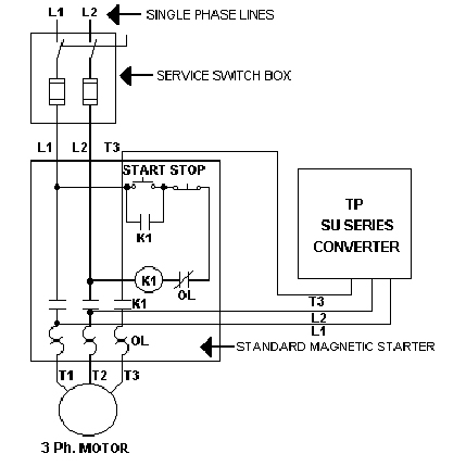
Follow the diagram above when
installing the TP phasing unit. The T3 line must be connected ahead of the
thermal overload on the line side of the contact. The leads marked L1 and
L2 are connected to the two energized phases of the contactor above the thermal
overload relays.

RT INSTALLATION INSTRUCTIONS
GENERAL
- Do not undersize your wire.
- Consult your utility company as to the size
and type of service entrance equipment that you will need. The
transformer which they provide must be large enough to supply the total
three phase load, single phase load, the occasional overload and converter.
- We prefer that you install the converter
indoors but this is not always possible. Many of our converters have
been running for years outside, however, a little shelter will greatly
increase the operating life.
- Use a safety switch or magnetic starter after
the main disconnect to start the converter.
- It is possible to up rate the converter by
using the power packs. Consult the factory for further information.
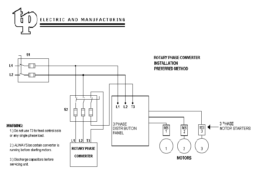
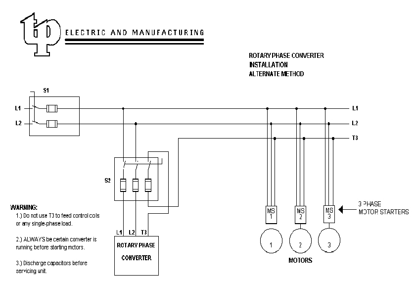
CONNECTIONS
- Connect L1 of the single phase power to L1 in
the junction box of the converter.
- Connect L2 of the single phase power to L2 in
the junction box of the converter.
- T3 is the manufactured phase and should be
color coded. The phase is not to be used for control coils, lights or
any other single phase load.
- The phase currents may fluctuate when other
motors are started and stopped. It is sometimes necessary to use the
next size larger heater coils.
- When the converter is running two motors, each
at the maximum horsepower rating, it is likely that one will require a power
pack. A power pack is an additional capacitor bank. The power
pack must always be applied at the load side of the starter so that it will
be energized only when that motor is operating. One lead from the
power pack connects with load terminal L2 and the other lead connects ahead
of the heater element to load terminal T3. Failure to install the
power pack correctly could damage the converter.
- Ground the converter frame.
OPERATING
- Line voltage must be within 10% of the voltage
rating of the converter (230VAC or 460VAC). Under no-load conditions
the manufactured T3 phase voltage may be 25% above the input voltage.
Under full load the manufactured T3 phase voltage may be 15% lower than the
input voltage.
- Always allows the converter to reach full
operating speed before starting any motors.
- Starting loads should not exceed the nameplate
rating of the converter. Smaller motors may be started together if the
total horsepower does not exceed the nameplate rating.
SERVICE
Very little service is required to maintain
the converter. Each bearing should be lubricated every 90 days with 1/4
ounce of Chevron Type SR1 or equivalent.
TROUBLESHOOTING
The converter will not start.
-
Check for low single phase line
voltage.
-
Check fuses.
-
Check the installation steps
again.
-
Check for a shorted oil
capacitor.
-
Check bearings.
-
Check for a damaged winding.
The load motor will not start.
-
Check for low single phase line
voltage.
-
Motor could be faulty.
-
Motor could be overloaded.
-
Check heaters.
-
Check for voltage drop.
Phase currents are greatly
unbalanced.
-
Check for low single phase line
voltage.
-
Converter may be overloaded.
-
A power pack my be required.
The converter or motor runs hot.
-
Check bearings.
-
Check for a damaged winding.
-
Make sure that the power pack is
properly connected.
-
There may be insufficient load
on the converter.
Full
Size
Full
Size